How to build a hydrogen storage system with high safety and reliability
The research on the safety and reliability of key energy storage components of hydrogen fuel cell vehicles has been widely concerned. In order to ensure the safety of hydrogen storage containers under high pressure conditions, the rational application of vehicle high pressure hydrogen storage containers is the focus of current research.
National standard GB/T 35544-2017 "Compressed Hydrogen Aluminum Liner Carbon Fiber Fully Wound Gas Cylinder for Vehicle" and group standard T/CATSI 02 007-2020 "Compressed Hydrogen Plastic Liner Carbon Fiber fully Wound Gas Cylinder for Vehicle" (hereinafter referred to as: This standard) specifies the requirements and qualified indexes of various types of tests for high-pressure hydrogen storage cylinders. Besides the fire test, the service performance test of type B high-pressure hydrogen storage cylinders is the only test item that uses hydrogen medium. The test system used is shown in Figure 1.
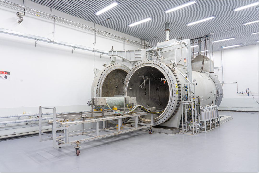
Figure 1-- Test system
The service performance test includes water pressure test, temperature and pressure circulation test at normal temperature and limit temperature, permeability test at limit temperature, static pressure test at normal temperature and hydraulic bursting test of residual strength, which are carried out in the sequence of Figure 2.
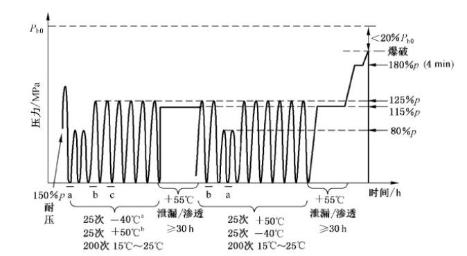
Figure 2- Usage performance test diagram
Among them, according to the environmental temperature, normal temperature and limit temperature pressure cycle test is mainly divided into low temperature condition, normal temperature condition and high temperature condition. Combined with the temperature division of the test medium, it will be further subdivided into four types: normal temperature + low temperature condition, low temperature + low temperature condition, low temperature + normal temperature condition, low temperature + high temperature condition. Taking low temperature + low temperature condition (hereinafter referred to as double low temperature condition) as an example, the performance test of high pressure hydrogen storage cylinder on vehicle will be further introduced.
When the double low temperature condition is developed, a temperature sensor is arranged in the mouth valve, the middle of the cylinder and the tail of the cylinder, so as to monitor the surface temperature of the cylinder in real time during the test. Note: Due to the winding of carbon fiber, the cylinder body has a certain degree of concave and convex. It is recommended to apply a layer of thermal silicone grease between the temperature sensor and the cylinder body to increase the contact area between the temperature sensor and the cylinder. At the same time, the temperature sensor of the bottle valve should be connected to the test system. It can monitor and control the charging and discharging rate of the test system.
In terms of safety, because the cylinder body will undergo radial deformation during the filling process of the test cylinder, in order to reduce the safety risk of the test, a pull wire displacement sensor is arranged at each end of the center line of the cylinder, and the pull wire is wrapped around the bottle, so as to monitor the deformation of the cylinder in real time and throughout the test process. See Figure 3
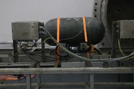
Figure 3-- Diagram of sensor distribution
According to the requirements of this standard, set the charging rate, the upper pressure limit (56MPa) and the number of cycles (5/15/25), and set the ambient temperature of gas cylinder test (-40℃) and the temperature of pre-cooled hydrogen gas (-40℃). Note: Subsequent pressure cycle tests can be carried out only when the tested gas cylinder and its accessories reach the specified temperature. See Figure 4 for specific cyclic curves
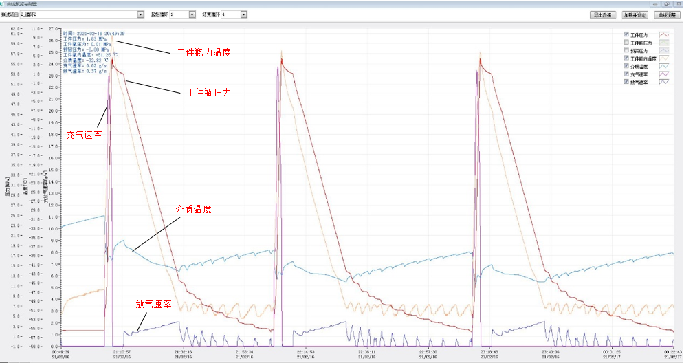
As can be seen from the test curve, when the test cylinder is rapidly filled from the initial pressure of 2MPa to the test pressure of 56MPa within 3 minutes, the temperature inside the test cylinder rises to 10℃, and the inflation rate is maximum (23-25) g/s. At the same time, the radial expansion of the test cylinder during the whole inflation process is 5-6mm. During the venting process, the test cylinder is vented at the rate of (2.12-2.16) g/s, and it takes about 45min for the pressure to drop to 2MPa. After monitoring, the temperature inside the cylinder will be reduced to -51.25℃, and the temperature of the cylinder valve and the middle and rear of the cylinder can be reduced to -46.67℃, -43.34℃, and -45.21℃ respectively.
In general, in the most severe working conditions such as double low temperature, the single cycle time is about 50min-1.5h according to the volume of the cylinder, and the test indexes are within the standard requirements.
It is worth noting that in the venting stage, the temperature of the cylinder and its accessories reaches below -40℃. When verifying the bottle valve, it is necessary to further consider the performance and functional integrity of the bottle at lower temperatures, which also brings a test to the current sealing materials.


 Sally He
 Sally He
 Sally He